コントローラソフトウェア
システムブロック
システムブロックは図1の通りです。LCDはI2C、SDカードはSPIで制御します。充電ユニットとの通信はUART2で行います。 充電ユニットは4ユニットあるので、アナログスイッチのUART選択回路で接続先を切り替えます。UART1はデバッグ用です。 LEDの点灯制御とスイッチの入力はGPIOで行います。T0は1msec周期のシステム全体のティックをカウントします。
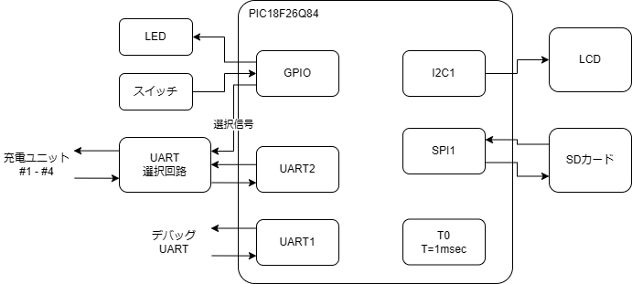
図1 システムブロック図
ソフトウェアモジュール
ソフトウェアモジュールは図2の通りで、各モジュールの説明は表1の通りです。
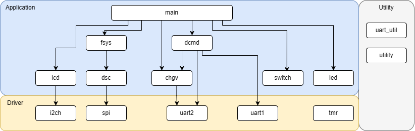
図2 ソフトウェアモジュール図
| レイヤ | モジュール名 | 説明 |
|---|---|---|
| ドライバ | i2ch | I2Cの制御モジュール。I2Cのホストの通信機能を提供する。 |
| ドライバ | spi | SPIの制御モジュール。SPIのホストの通信機能を提供する。 |
| ドライバ | uart2 | UART制御モジュール。UARTの送受信機能を提供する。リングバッファを用いた割り込みで送受信を行う。 充電ユニットの制御に使用する。制御対象の充電ユニットは、外付けのアナログスイッチにより選択される。 | ドライバ | uart1 | UART制御モジュール。UARTの送受信機能を提供する。リングバッファを用いた割り込みで送受信を行う。 デバッグコマンドの通信に使用する。 |
| ドライバ | tmr | TMR制御モジュール。T0は1msec周期でシステムティック用のカウンタでフリーランする。 また、1msecの割り込みでシステムティックがインクリメントされる。 |
| アプリ | lcd | LCDの制御を行うモジュール。16文字x2行のバッファに書き込まれた文字をLCDに表示する。 |
| アプリ | dsc | SDカードモジュール。SDカードのSPIモードのコマンド・レスポンスの通信を行う。 |
| アプリ | fsys | ファイルシステムモジュール。FAT32準拠のロギング用ファイルシステムを提供する。 |
| アプリ | chgv | 充電変数モジュール。充電ユニットと通信し、充放電に関連する設定値の設定や、充放電状態の取得の機能を提供する。 |
| アプリ | dcmd | デバッグコマンドジュール。UARTのデバッグコマンドを処理するモジュール。 充電コントローラ自体のデバッグ機能と、各充電ユニットのデバッグ機能へのアクセスを提供する。 |
| アプリ | switch | スイッチ状態読み取りモジュール。ポーリングで、スイッチ状態を読みより、押し下げ、長押しの状態を判断する。 |
| アプリ | led | LEDの制御モジュール。指定された点灯モード(点灯、消灯、点滅)で書き込みLED、ステートLEDの点灯を制御する。 |
| アプリ | main | メインモジュール。メインループで充放電の制御、SDカードへの書き込み、LEDの制御、スイッチの読みとりを行う。 |
| ユーティリティ | uart_util | UARTユーティリティモジュール。utilityモジュールの関数を呼び出して、UARTでの数値、文字列の出力機能を提供する。 |
| ユーティリティ | utility | ユーティリティモジュール。主に数値、文字列の変換関数を提供する。 |
充電ステート
Fig.3 shows Charge unit state transition diagram. The explanation of each state is listed in Table.1.
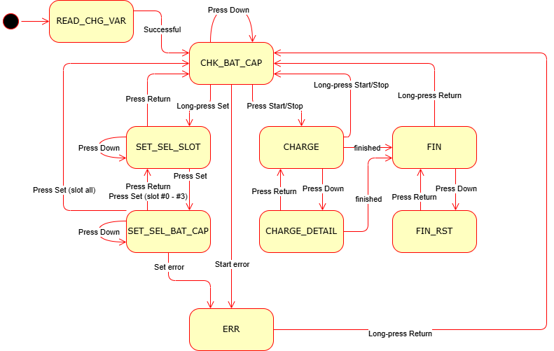
Fig.3 Charge Unit State Transition Diagram
| Value | State | Description |
|---|---|---|
| 0 | READ_CHG_VAR | Read charge variable state. Aftrer the power on, the system enters this state. If the chage variables of all units are read successfully, transits to ST_CHK_BAT_CAP state. |
| 1 | CHARGE | Charge state. The system checkes the charge states of all units. If all units finshed charging, stansits to FIN state. If down button is pressed, transits to CHARGE_DETAL state. If start/stop button is long-pressed, sends reset commands to all units. If the reset commands are succeeded, transits to READ_CHG_VAR state. |
| 2 | CHARGE_DETAIL | Charge detail state. Basically this state is the same as CHARGE state. But the detail state of one unit is displayed. If down button is pressed, the displayed slot is changed. The slot is changed as 0 -> 1 -> 2 -> 3 -> 0 -> ... . If start/stop button is long-pressed, sends reset commands to all units. If the reset commands are succeeded, transits to READ_CHG_VAR state. If return button is pressed, transits to CHARGE state. |
| 3 | CHK_BAT_CAP |
Check battery capacity state. User should check the battery capacity settings of all slots in this state. If start/stop button is pressed, send chage start command to all units. If charge start commands for all units are succeeded, transits to CHARGE state. If down button is pressed, the displayed slot is changed. The slot is chnaged as 0 -> 1 -> 2 -> 3-> 0 -> ... . If set button is long-pressed, transits to SET_SEL_SLOT state. |
| 4 | SET_SEL_SLOT |
Set / Select slot state. User select the slot to set the battery capacity. If down button is pressed, the slot to set is changed. The slot is changed as all -> 0 -> 1 -> 2 -> 3 -> all -> ... . If set button is pressed, transits to SET_SEL_BAT_CAP state. If return button is pressed, transits to CHK_BAT_CAP state. |
| 5 | SET_SEL_BAT_CAP |
Set / Select battery capacity state. User select the batter capacity to set the battery capacity. If down button is pressed, the capacity is changed. The capacoty is changed from 2500mA to 500mA per 50mA. After 500mmA, it resets to 2500mA. If set button is pressed and the selected slots are all, the selected capacity is set to all slots, and transits to SET_SEL_BAT_CAP state. If set button is pressed and the selected slot is not all, the selected capacity is set to the selected slot, and transits to SET_SEL_SLOT state. If return button is pressed, transits to SET_SEL_SLOT state. |
| 6 | FIN |
Finished state. The summay charge results are displayed. If down button is pressed, tansits to FIN_RST. If return button is long-pressed, sends reset commands to all units. If the reset commands are succeeded, transits to READ_CHG_VAR state. |
| 7 | FIN_RST |
Finished / Result state. The detail charge results are displayed. If down button is pressed, the displayed slot is changed. The slot is changed as 0 -> 1 -> 2 -> 3 -> 0 -> ... . If return button is pressed, transits to FIN state. |
| 8 | ERR |
Error state. This stats indicates the system error occurred. |