充電ユニットソフトウェア
システムブロック
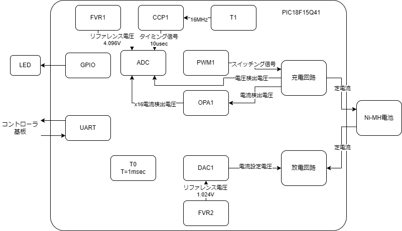
図1 システムブロック図
ソフトウェアモジュール
ソフトウェアモジュールは図2の通りで、各モジュールの説明は表1の通りです。
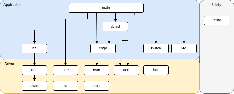
図2 ソフトウェアモジュール図
| レイヤ | モジュール名 | 説明 |
|---|---|---|
| ドライバ | adc | ADC制御モジュール。充電時は、10usecごとの割り込みで、電流検出電圧と電池電圧のADCを行い、 フィードバック制御を行い、PWMのDUTYを計算する。 |
| ドライバ | pwm | PWM制御モジュール。周期40kHzで、指定されたDUTYのPWMを生成する。 |
| ドライバ | dac | DAC制御モジュール。リファレンス電圧1.024Vで指定されたステップ値でDAC出力を行う。 DACの分解能は4mV。 |
| ドライバ | fvr | FVR制御モジュール。FVR1は4.096V出力、FVR2は1.024V。 |
| ドライバ | nvm | NVM読み書きを行うモジュール。 |
| ドライバ | opa | オペアンプ制御モジュール。電流検出電圧のADCのため、ADCの前段として16倍の非反転増幅回路を実現する。 |
| ドライバ | uart | UART制御モジュール。UARTの送受信機能を提供する。リングバッファを用いた割り込みで送受信を行う。 デバッグコマンドの通信に使用する。 |
| ドライバ | tmr | TMR制御モジュール。T0は1msec周期でシステムティック用のカウンタでフリーランする。 また、1msecの割り込みでシステムティックがインクリメントされる。 |
| アプリ | chgv | 充電変数モジュール。充放電に関連する設定値や、充放電状態を保持するモジュール。 NVMへの設定値の保存、NVMからの読み込みの機能を提供する。 |
| アプリ | dcmd | デバッグコマンドジュール。UARTのデバッグコマンドを処理するモジュール。 主にchgvモジュールが保持する設定値の読み書きや、充放電制御、状態読み取りのコマンドを提供する。 |
| アプリ | switch | スイッチ状態読み取りモジュール。ポーリングで、スイッチ状態を読みより、押し下げ、長押しの状態を判断する。 |
| アプリ | led | LED制御モジュール。指定された点灯モード(点灯、消灯、点滅)でLEDの点灯を制御する。 |
| アプリ | main | メインモジュール。メインループで充放電の制御、LEDの制御、スイッチ状態の読み取りを行う。 |
| ユーティリティ | utility | ユーティリティモジュール。主に数値、文字列の変換関数を提供する。 |
充電ステート
Fig.3 shows Charge unit state transition diagram. The explanation of each state is listed in Table.1.
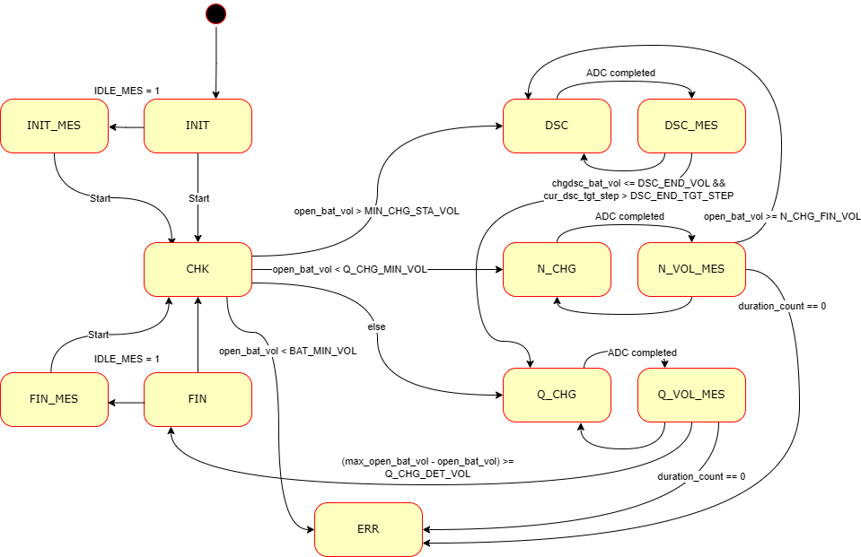
Fig.3 Charge Unit State Transition Diagram
| Value | State | Description |
|---|---|---|
| 0 | INIT | Initilal state. Aftrer the power on, the system enters this state. If IDLE_MES flag is set, transits to INIT_MES state. If start/stop button is pressed, transits to CHK state. |
| 1 | INIT_MES | Initial measurement state. The system measures the voltage for debug purpose. If start/stop button is pressed, transits to CHK state. |
| 2 | CHK | Check state. The system measures the battery voltage and judges the following process. If the battery voltage is lower than BAT_MIN_VOL, transits to ERR state. If the battery voltage is higher than MIN_CHG_STA_VOL, transits to DSC state. If the battery voltage is lower than Q_CHG_MIN_VOL, transits to N_CHG state. Othewise, transits to Q_CHG state. |
| 3 | DSC |
Discharge state. The system is discharging the battery and measuring the battery voltage during the discharge. After the discharge duration (92msec) passes, transits to DSC_MES state. |
| 4 | DSC_MES |
Discharge measurement state. The system is measureing the battey with no connection (open battery voltage). If the battery voltage is eqauls to or less than DSC_END_VOL, sets the discharge current the half of the current value and continue the discharge. If the discharge current is equals to or less than DSC_END_TGT_STEP, transits to Q_CHG state. |
| 5 | N_CHG |
Normal charge state. The system charges the battery with 0.1C (or 0.2C*) current and measures the battery voltage during the charge. * If the battery capacity is equals to or less than 700mA, 0.2C is selected. After the charge duration passes, transits to N_VOL_MES state. |
| 6 | N_VOL_MES |
Normal charge measurement state. The system is measureing the battey with no connection (open battery voltage). If the battery voltage is equlas to or higher than N_CHG_FIN_VOL, starts the quick charge. If the charge duration exceeds N_CHG_TIME, enters the error state. |
| 7 | Q_CHG |
Quick charge state. The system charges the battery with 0.5C (or 1.0C*) current and measures the battery voltage during the charge. * If the battery capacity is equals to or less than 700mA, 1.0C is selected. After the charge duration passes, transits to Q_VOL_MES state. |
| 8 | Q_VOL_MES |
Quick charge measurement state. If the charge duration exceeds Q_CHG_TIME, transits to ERR state. The maximum battery voltage is recorded, and the current measured voltage is equlas to or less than Q_CHG_DET_VOL from the maximum voltage, transits to FIN state. |
| 9 | FIN |
Finished state. If IDLE_MES flag is set, transits to FIN_MES state. If start/stop button is pressed, transits to CHK state. |
| 10 | FIN_MES | Finished measurement state. The system measures the voltage for debug purpose. If start/stop button is pressed, transits to CHK state. |
| 11 | ERR | Error state. If start/stop button is long-pressed, transits to CHK state (reset operation). |
| 12 | N_CHG_VOL_TST |
Normal charge voltage test state. This state is almost same as N_CHG state. The system doesn't do the error check and contiues to PWM control with N_CHG_TGT_VOL. This state is to check waveform of normal charge configuration. The entering to or exiting from this state can be done only by the debug command. |
| 13 | Q_CHG_VOL_TST |
Quick charge voltage test state. This state is almost same as Q_CHG state. The system doesn't do the error check and contiues to PWM control with N_CHG_TGT_VOL. This state is to check waveform of quick charge configuration. The entering to or exiting from this state can be done only by the debug command. |
| 14 | N_CHG_TST |
Normal charge test state. N_CHG_TST and N_CHG_VOL_MES_TST states are the almost same as N_CHG and N_VOL_MES states. But there are no transition to other states. This is for PWM and ADC control debug of normal charge. The entering to or exiting from N_CHG_TST and N_CHG_VOL_MES_TST states loop can be done only by the debug command. |
| 15 | N_CHG_VOL_MES_TST |
Normal voltage measurement test state. Please see N_CHG_TST. |
| 16 | Q_CHG_TST |
Quick charge test state. Q_CHG_TST and Q_CHG_VOL_MES_TST states are the almost same as Q_CHG and Q_VOL_MES states. But there are no transition to other states. This is for PWM and ADC control debug of quick charge. The entering to or exiting from Q_CHG_TST and Q_CHG_VOL_MES_TST states loop can be done only by the debug command. |
| 17 | Q_CHG_VOL_MES_TST |
Quick voltage measurement test state. Please see Q_CHG_TST. |
| 18 | DSC_TST |
Discharge test state. This state is almost same as DSC state. The system doesn't do the error check and continues the discarge with DSC_TGT_STEP. This state is to check discharg circuit functionality. The entering to or exiting from this state can be done only by the debug command. |
| 19 | OFF_CAL |
Offset calibration state. This state is for OPA offset calibration. PWM is disabled, 5V is connected to battery plus terminal, and ADC measures the voltage of normal charge detection resistor. The entering to or exiting from this state can be done only by the debug command. |
| 20 | VOL_MES_TST |
Voltage measurement state. This state is almost same as CHK state. But the system doesn't do the error check and the transition to the other states. This is to check the open battery voltage measurement functionality. The battery plus terminal is unconnected. ADC measures the voltage of normal charge detection resistor. The entering to or exiting from this state can be done only by the debug command. |